THE NERC MST RADAR FACILITY AT ABERYSTWYTH
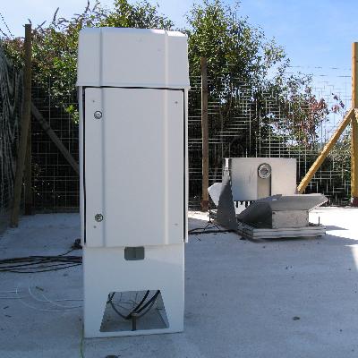
The Facility has been operating a Vaisala LD40 laser ceilometer (the upright white instrument to the left in the above image) at the radar site since 8th August 2005. Backscatter data have been recorded in addition to the standard cloud base data since 24th April 2007. However, the former will not be made available through the BADC until they have been rewritten into self-documented netCDF files (the cloud base data are already available in NASA-Ames format files). Please contact the NERC MST Radar Facility Project Scientist if you have an immediate need for the backscatter data. An example plot is shown at the bottom of this page.
The LD40 operates according to the Light Detection and Ranging (LIDAR) principle, which is similar to that of radar. It transmits short pulses of laser light which are scattered back to the instrument from atmospheric targets. The distance of the targets from the instrument is determined by the time delay between the transmission and reception of a pulse. The instrument is vertically-pointing and so the distance gives a measure of the altitude of the targets above mean sea level. The main targets are aerosols (e.g. small soot or dust particles), water droplets, snow flakes and ice crystals. Aerosol concentrations tend to be high within the boundary layer leading to laser returns from a continuum of low-level altitudes. Aerosol concentrations tend to be much lower within the over-lying free atmosphere and so significant laser returns are only subsequently detected from cloud layers. The vertical profile of the receiver signal amplitude may consequently be used to determine cloud base altitudes. If a cloud layer is sufficiently optically thin that it does not not fully attenuate the transmitted pulses, subsequent cloud layers may be detected.
The LD40 transmits 75 ns duration pulses at a repetition frequency of 6494 Hz. The temperature of the laser diode is maintained within a narrow range in order to ensure high stability of the emitted wavelength. This allows a very narrow band optical filter to be used at the input to the receiver. The receiver signal amplitude is sampled at time intervals of 50 ns, corresponding to altitude intervals of 7.5 m. Owing to the low power of the transmitter, the receiver signal amplitude for a single pulse backscattered from a high-altitude cloud is not sufficiently large to be distinguished above the noise level. Nevertheless the contribution from cloud backscatter remains coherent from pulse to pulse, whereas that from noise varies randomly. Consequently the detectability of the desired signal can be greatly improved by summing the receiver signal amplitude (separately for each altitude interval) over all pulses within a 15 s interval. Attention is restricted to altitudes below 13.05 km (corresponding to maximum range of detection of 13.00 km - the instrument is at 50 m above mean sea level) since, even after summation, the presence of any clouds which might exist at higher altitudes can only be determined with difficulty.
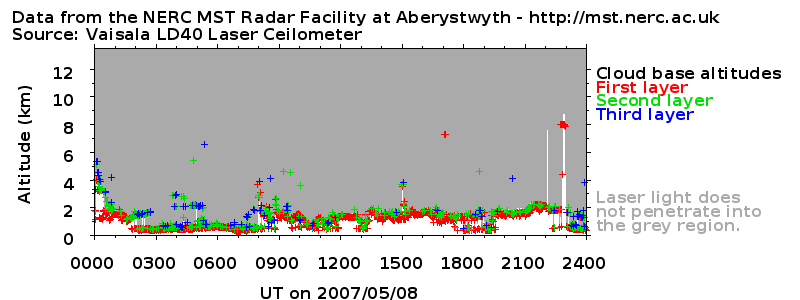
The instrument manufacturer's cloud detection algorithm is applied to the 15 s receiver signal amplitude profiles. It is designed to detect up to three possible cloud layers. For each of these, the altitude (above mean sea level) of the cloud base and the depth to which the laser light penetrates is determined. If the laser light is not able to penetrate the entire depth of a particular cloud layer, missing datum values are given for subsequent layers. If no cloud layer is detected, missing datum values are given for all three layers. In order to distinguish between cloud-free conditions and a lack of observations, attention should be paid to instrument status flag. An estimate is also given of the maximum possible altitude of cloud detection and of the visibility for a human observer looking upwards. The maximum range of cloud detection defaults to 13.05 km under clear sky conditions. A lower value implies that no information may be given on any cloud layers which may exist beyond this altitude. Under such conditions there is also a limit to the visibility for a human observer. Otherwise a missing datum value is given. Finally, an estimate is given of the precipitation rate based on the characteristics of the backscatter profile. A value of 0 implies no precipitation and a value of 3 suggests heavy precipitation.
The instrument sends a data message to a logging computer every 15 s. Date-time stamps are provided by the instrument's internal clock rather than by the computer's. They contain fields for hours and minutes but not for seconds. Only one of the 4 messages for each minute is saved. The instrument's internal clock can only be synchronised manually. Since this requires a special connection to be made via the serial service interface, it is only done on an infrequent basis. The accuracy of the internal clock's time decreases with increasing time.
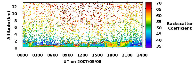
Example cloud base and backscatter data plots for 8th May 2005.
The backscatter coefficient represents the (scaled) natural logarithm of the range-squared-corrected receiver signal power. The speckling above 2 km altitude represents noise, which appears to vary diurnally.